
Shaders
These three lines are exactly how we create a shader.
int shaderID = GL20.glCreateShader(GL20.GL_VERTEX_SHADER or GL20.GL_FRAGMENT_SHADER);
// shaderSource is a string
GL20.glShaderSource(shaderID, shaderSource);
GL20.glCompileShader(shaderID);And the code below tells you the status of your shader.
if (GL20.glGetShaderi(shaderID, GL20.GL_COMPILE_STATUS) == GL11.GL_FALSE)
String errorLog = GL20.glGetShaderInfoLog(shaderID, 1024);However, having a shaderID is not enough. We want a shader program. We will attach a vertex shader and a fragment shader to the shader program, defining the rendering pipeline.
If you are wondering what are vertex and fragment shaders, take a look at the picture below. 
All you need to know is that Frag is a shading stage after Vert, and we can pass data from the vertex shader (VS) to the fragment shader (FS). For instance, we pass the texture UV (e.g. vec2) from VS to FS.
You might be wondering how come FS is able to draw a compact region with discrete data. Answer: interpolation.
Say A=(x1, y1), B=(x2, y2), C=(x3, y3), then P = λ1*A + λ2*B + λ3*C where Σλi=1, and P is in ABC.
And this is how you get the colorful "hello triangle" 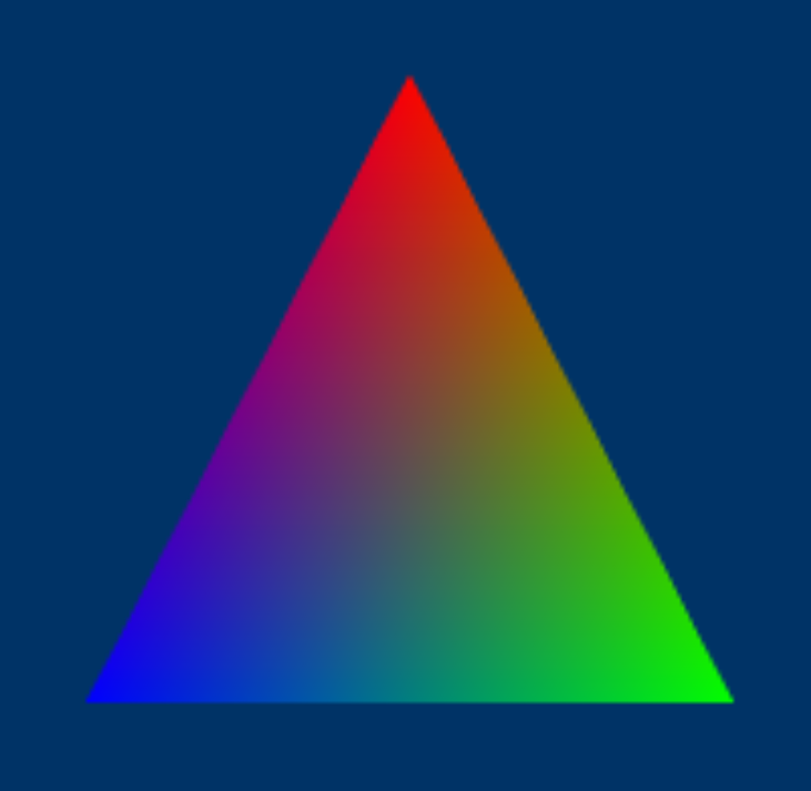
Shader Program
Don't forget to attach both vertex and fragment shader id.
int programID = GL20.glCreateProgram();
GL20.glAttachShader(programID, shaderID);
GL20.glLinkProgram(programID);When you want to use the shader program.
GL20.glUseProgram(programID);

// pass uniforms to the shader

// render

GL20.glUseProgram(0); // 0 stands for "no shader"/"null shader"What are uniforms? Let's say you have a line of code uniform bool flag; in your shader. Then, you'll need to do the following.
int loc = GL20.glGetUniformLocation(programID, "flag");
GL20.glUniform1i(1 or 0); // which is true or falseAfter that, the flag in your shader is set to true or false.
Notice:
- You can only pass uniforms when you are using that shader program
- Unused uniforms will most likely be deleted by GL so
glGetUniformLocationwill return-1(depends on driver)
Disposing Shaders
You better dispose all the GL related resources at the end.
GL20.glDetachShader(programID, shaderID);
GL20.glDeleteShader(shaderID);
GL20.glDeleteProgram(programID);EG1
We'll write the actual shaders we used in Drawing Tris Using Vertices and Indices Via The Modern Pipeline here.
Vertex shader
#version 330 core

layout (location = 0) in vec3 pos;
layout (location = 1) in vec2 texCoord;
layout (location = 2) in vec3 normal;

out vec2 TexCoord;
out vec3 FragNormal;

void main()
{
    gl_Position = vec4(pos, 1.0);

    TexCoord = texCoord;
    FragNormal = normal;
}Fragment shader
#version 330 core

out vec4 FragColor;

void main()
{
    // tex coord isn't used for simplicity
    // you need to pass a uniform (`uniform sampler2D tex;`) and fetch pixels from tex
    FragColor = vec4(1.0, 0.5, 0.2, 1.0);
}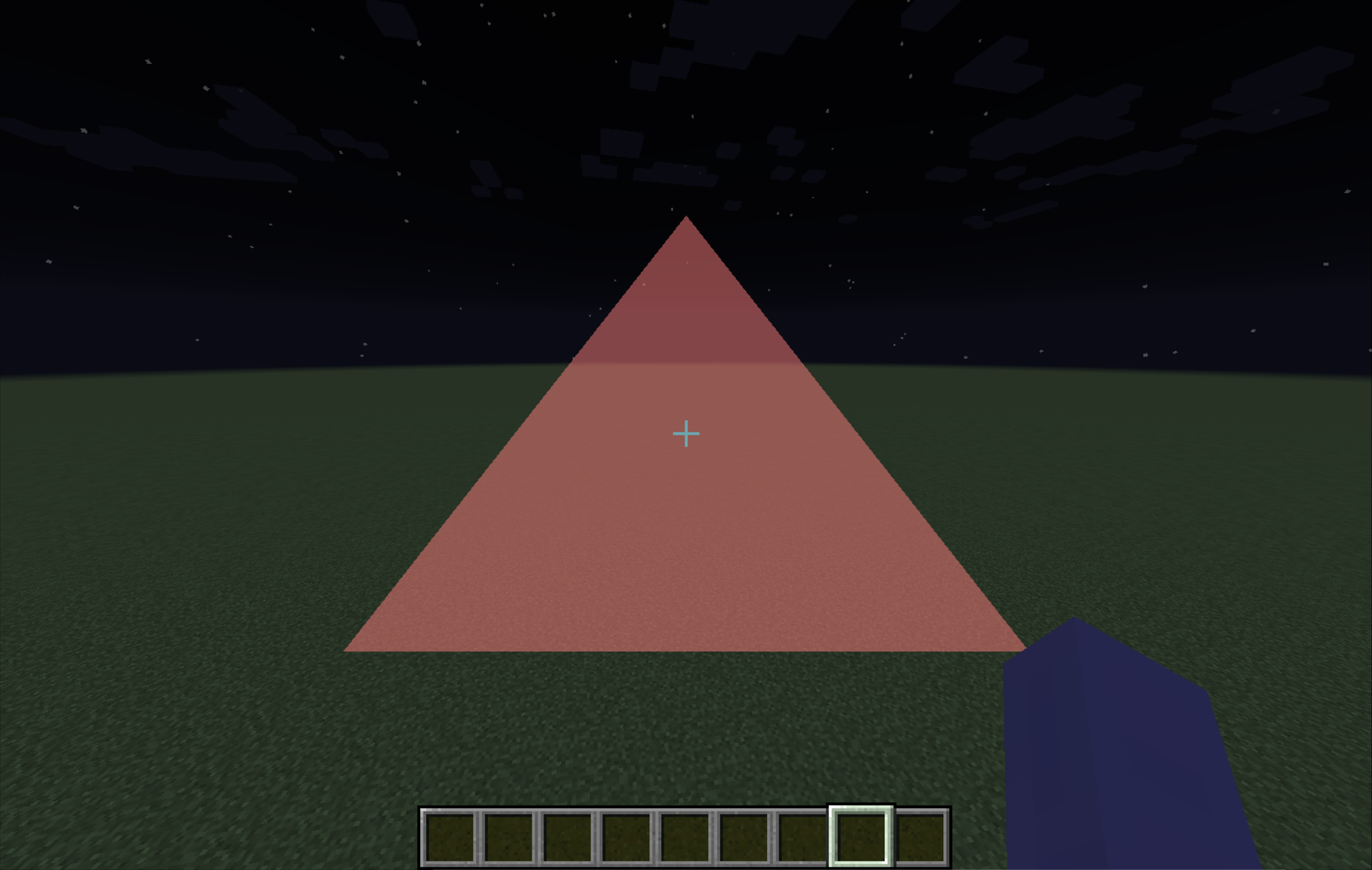
As we can see, the geometry is totally defined by
gl_Position. But why is it avec4?
Just a quick clarification,gl_Positionis in clip space, and it's a 4D homogenous coordinate.
Vertices like
-0.5f, -0.5f, 0.0fare small numbers, but why the triangle is huge?
Another quick clarification, those vertices are in NDC (normalized device coordinate)
Space Range What it Means NDC X -1 Left edge of the viewport NDC X 1 Right edge of the viewport NDC Y -1 Bottom edge of the viewport NDC Y 1 Top edge of the viewport NDC Z -1 Near clipping plane (closest depth) NDC Z 0 Middle of the depth range NDC Z 1 Far clipping plane (farthest depth) Usually vertices are transformed from world space to clip space in the vertex shader. The GPU then performs perspective division to obtain NDC (
NDC = clip/clip.w), followed by viewport transform and rasterization. Finally, FS receives interpolated attributes, not NDC coordinates.
 Nullpinter